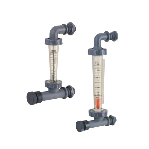
The electromagnetic flowmeter is a flowmeter that performs flow measurement according to Faraday's law of electromagnetic induction. The advantage of the electromagnetic flowmeter is that the pressure loss is extremely small and the measurable flow range is large. The ratio of the maximum flow rate to the minimum flow rate is generally above 20:1. The applicable industrial pipe diameter range is wide, up to 3m. The output signal is linear with the measured flow rate, and the accuracy is high. It can measure the conductivity ≥5μs/cm The fluid flow of acid, alkali, salt solution, water, sewage, corrosive liquid and mud, mineral pulp, paper pulp, etc. But it cannot measure the flow of gas, steam and pure water.
When a conductor cuts the lines of force in a magnetic field, an induced electric potential will be generated in the conductor. The magnitude of the induced electric potential is proportional to the effective length of the conductor in the magnetic field and the speed at which the conductor moves in the magnetic field perpendicular to the direction of the magnetic field. In the same way, when the conductive fluid flows in the vertical direction in the magnetic field to cut the magnetic induction force lines, it will also generate an induced electric potential on the electrodes on both sides of the pipeline. The direction of the induced potential is determined by the right-hand rule, and the magnitude of the induced potential is determined by the following formula:
Ex=BDv-----------------Equation (1)
In the formula Ex-induced potential, V;
B—Magnetic induction intensity, T
D—pipe inner diameter, m
V—The average flow velocity of the liquid, m/s
However, the volume flow rate qv is equal to the product of the fluid velocity v and the pipe cross-sectional area (πD²)/4. Substituting equation (1) into this equation gives:
Qv=(πD/4B)* Ex ---------Equation (2)
It can be seen from the above formula that when the pipe diameter D is fixed and the magnetic induction intensity B remains unchanged, the measured volume flow has a linear relationship with the induced potential. If an electrode is inserted on both sides of the pipe, the induced potential Ex can be introduced, and the volume flow can be obtained by measuring the magnitude of this potential.
According to the principle of Faraday electromagnetic induction, a pair of detection electrodes are installed on the tube wall perpendicular to the axis of the measuring tube and the magnetic line of force. When the conductive liquid moves along the axis of the measuring tube, the conductive liquid cuts the magnetic line of force to generate an induced electric potential. This induced electric potential consists of two The detection electrode detects that the value is proportional to the flow rate, and its value is:
E=B·V·D·K
Where: E-induced electric potential;
K-coefficient related to magnetic field distribution and axial length;
B-Magnetic induction intensity;
V-average flow velocity of conductive liquid;
D-electrode distance; (inner diameter of measuring tube)
The sensor uses the induced electric potential E as a flow signal and transmits it to the converter. After signal processing such as amplification, conversion and filtering, the instantaneous flow and cumulative flow are displayed by a dot matrix liquid crystal with backlight. The converter has 4-20mA output, alarm output and frequency output, and is equipped with communication interfaces such as RS-485, and supports HART and MODBUS protocols.
Note: The parameters of different electromagnetic flowmeters are slightly different, please be sure to check the manual when using.
According to Faraday’s law of electromagnetic induction, in a uniform magnetic field with a magnetic induction intensity of B, a non-magnetic pipe with an inner diameter of D is placed perpendicular to the direction of the magnetic field. When the conductive liquid flows in the pipe at a flow rate v, the conductive fluid cuts the magnetic lines of force. Installing a pair of electrodes on the pipe section perpendicular to the diameter of the magnetic field can prove that as long as the flow velocity distribution in the pipe is an axisymmetric distribution, an induced electromotive force is generated between the two electrodes:
e=KBDv (3-36)
In the formula, v is the average flow velocity on the pipe section, and k is the instrument constant. The volume flow rate of the pipeline can be obtained as:
qv = πeD/4KB (3-37)
It can be seen from the above formula that the volume flow qv has a linear relationship with the induced electromotive force e and the inner diameter of the measuring tube D, is inversely proportional to the magnetic induction intensity B of the magnetic field, and has nothing to do with other physical parameters. This is the measuring principle of electromagnetic flowmeter.
It should be noted that, to make formula (3-37) strictly true, the measurement conditions of the electromagnetic flowmeter must meet the following assumptions:
① The magnetic field is a uniformly distributed constant magnetic field;
②Axisymmetric distribution of the flow velocity of the fluid being measured;
③The liquid to be tested is non-magnetic;
④The conductivity of the tested liquid is uniform and isotropic.


 English
 中文简体
中文简体 русский
 España